- Summary
- Parameters
- Size chart
- Model order
- Download
- Communication
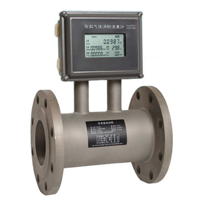
LWQ Gas Turbine Flowmeter
Overview
Gas turbine flowmeter is a velocity instrument. It has high accuracy, good repeatability, simple structure, wide measurement range, small size, light weight, small pressure loss, and easy to maintain. It can be widely used in petroleum, chemical industry, metallurgy, city gas pipeline network and other industries. It has been widely applied, especially in city gas metering, and the metering of transmission pipe network and gas regulator station.
Working Principle
Gas turbine flowmeter places turbine in the measured fluid, when the gas flows through the meter, the gas was accelerated and rectified under the action of the rectifier with the special structure. The impeller is rotated by the force that the gas acted on the impeller; the blade on the impeller makes the magnetic resistance of magnetic circuit change periodically. The angular velocity of impeller in a certain range of flow is proportional to the flow. On the basis of electromagnetic induction principle, the flow meter inducts the pulse signal which is proportional to the volume flow of the fluid, the signal will be amplified and rectified by the pre-amplifier then be accumulated by the single chip, displayed on the LCD screen and then the pulse signal will be also input with the signal detected by the temperature and pressure sensor into the totalizer to do the accumulate processing, at last display the result on the LCD screen.
Main Technical Parameters
|
Specification and Model |
Nominal Diameter (mm) |
Working Pressure MPa |
Startup Flow (m3/h) |
Flow Range |
Installation Method |
|
LWE-40XL LWE-40XH |
40 |
1.6 2.5 4.0 6.3 10 16 26 42 |
1.8 2.5 |
2.5-50 5-100 |
Thread Flange |
|
LWE-50 XL LWE-50 XH |
50 |
2.5 5 |
5-100 10-200 |
Flange |
|
|
LWE-50 XL LWE-50 XH |
80 |
6 10 |
10-240 20-480 |
||
|
LWE-100 XL LWE-100 XH |
100 |
8 12 |
12-360 27-720 |
||
|
LWE-150 XL LWE-150 XH |
150 |
10 15 |
35-1000 50-2000 |
||
|
LWE-200 XL LWE-200 XH |
200 |
35 60 |
60-1500 100-4000 |
||
|
LWE-250 XL LWE-250 XH |
250 |
40 |
75-3500 Customized |
Installing Boundary and Dimension
|
40 |
50 |
80 |
100 |
150 |
200 |
250 |
|
|
A (mm) |
140 200 |
200 |
200 |
220 |
300 |
300 |
400 |
|
H (mm) |
250 |
300 |
350 |
400 |
450 |
450 |
500 |
Ordering Model
|
1 |
2 |
3 |
Illustration |
|
|
Nominal Diameter |
Nominal Pressure |
Connecting Mode |
||
|
LWQ |
|
|
|
Gas turbine |
|
|
4~450mm |
|
|
Nominal diameter 4~450mm |
|
|
|
1.6~42 |
|
Nominal pressure 1.6~42MPa |
|
|
|
|
A |
Indication sensor |
|
|
|
|
B |
Field display type |
|
|
|
|
C |
Temperature and pressure compensation |