- Summary
- Parameters
- Size chart
- Model order
- Download
- Communication
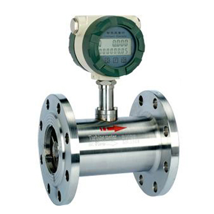
LWGY Turbine Flowmeter
Overview
LWGY Series Liquid Intelligent Turbine Flowmeter is composed of turbine flow sensor and intelligent display instrument which receives electrical pulse signal. It was used to measure the volume flow and total flow of the low viscosity liquids in closed conduits, and it was widely used in petroleum, chemical industry, metallurgy, aviation, scientific research and other departments.
Operating Principle
When the measured fluid flows through the sensors, the impeller in the sensor will be rotated by the kinetic energy of the liquid. At this point, the impeller blades make the magnetic resistance of the detection device change periodically, thus the electric pulse signal that the frequency is proportional to the flow will be inducted at the both ends of coil, it will be amplified by the amplifier then output by remote transmission. Within the measuring range, the flow pulse frequency of the sensor is proportional to the volume flow; this ratio is the meter coefficient, represented by K.
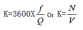
In the formula: f-the frequency of the flow signal (Hz)
Q-number of pulses
V-total volume (m3 or L)
Main Technical Parameters
|
Nominal Diameter DN (mm) |
Flow Range m3/h |
Working Pressure MPa |
Method of Installation |
Accuracy |
Material |
|
4 |
0.04~0.25 |
1.6 2.5 4.0 6.3 10.0 16.0 26.0 42.0 |
Thread |
0.5 1 |
304 316 |
|
6 |
0.1~0.6 |
Thread |
0.5 |
||
|
10 |
0.2~1.2 |
Thread |
1 |
||
|
15 |
0.6~6 |
Thread, Flange |
0.5 |
||
|
20 |
0.8~8 |
Thread, Flange |
1 |
||
|
25 |
1~10 |
Thread, Flange |
0.5 |
||
|
40 |
2~20 |
Thread, Flange |
1 |
||
|
50 |
4~40 |
Thread, Flange |
0.5 |
||
|
80 |
10~100 |
1.6 2.5 4.0 6.3 |
Flange |
1 |
|
|
100 |
20~200 |
Flange |
0.5 |
||
|
150 |
30~300 |
Flange |
1 |
||
|
200 |
80~800 |
Flange |
0.5 |
Installing Boundary and Dimension
|
Inside Nominal Diameter (mm) |
4 |
6 |
10 |
15 |
20 |
25 |
32 |
40 |
50 |
65 |
80 |
100 |
125 |
150 |
200 |
|
L (mm) |
50 |
50 |
50 |
75 |
85 |
100 |
120 |
140 |
150 |
175 |
200 |
220 |
250 |
300 |
360 |
|
H (mm) |
145 |
145 |
165 |
170 |
175 |
180 |
220 |
178 |
252 |
270 |
287 |
332 |
340 |
367 |
415 |
|
G |
R3/8 |
R3/8 |
R3/8 |
G1 |
G1 |
G1 |
G1 |
G2 |
|
|
|
|
|
|
|
|
LWGY |
Turbine Flowmeter |
|
|
Output Signal |
No mark |
Basic type (voltage pulse signal output) |
|
A |
4-20mA Frequency output, remote transmitting transmitter |
|
|
B |
Battery power supply, field display |
|
|
C |
Field display, 4-20mA Two-wire current output, remote transmitting type |
|
|
Nominal Diameter |
D4~200 |
D4~200mm |
|
Operating Environment |
B |
Explosion-proof type |
|
P |
Ordinary type |
|