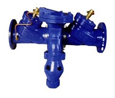
Backflow Preventer
Overview
Backflow preventer is composed of two separated check valves and a water escape valve with hydraulic transmission. Because of the local head loss of check valves, the pressure in middle cavity is always smaller than the pressure of water inlet. The differential pressure keeps the water escape valve closing, pipeline transmits water normally. When the pressure becomes abnormal (the pressure of water outlet is greater than the pressure in middle cavity), even though the two check valves cannot seal reversely, safe water escape valve can open automatically to exhaust all backflow water, and forms air block to ensure that the water from upstream is sanitary and safe.
Product Features
1. Unique design, artistic exterior, simple installation, convenient maintenance;
2. With two check valves and the function of air block, can prevent backflow contamination thoroughly under any operating conditions;
3. With accurate calculation, excellent machining, reliable performance, sensitive action;
4. Supports MODBUS TCP/MODBUS RTU gateway function.
5. Inside and outside surfaces are painted with environmental protection coating to ensure the corrosion prevention and security of the product.
Operating Principle
When the pressure in pipe network is normal, the water flows easily from inlet to outlet across two check valves. Because the local resistance of the first check valve makes the cavity’s pressure be slightly smaller than inlet’s pressure, and the water pressure under diaphragm is equal with inlet’s pressure, the water pressure under diaphragm is greater than the water pressure on diaphragm, safe water escape valve keeps closing and the water in pipeline flows normally. When all valves on the pipeline behind backflow preventer are closed, the water is in the motionless state. If inlet’s pressure does not change, and the cavity’s water pressure is also slightly smaller than inlet’s pressure, the safe water escape valve will also at closed state.
When the pressure in the pipeline behind backflow preventer increases and it is bigger than the pressure of supply water, called backpressure, if the second check valve do not leak, the high pressure water will not flow back to valve cavity, and the pressure in valve cavity will be the same as the pressure of normal flow, so the safe water escape valve do not exhaust water; if the second check valve leaks, the pressure in valve cavity will increase, the safe water escape valve will exhaust water. In this way, the pressure of high pressure flow on the first check valve is decreased, and the rear water is prevented flowing back to front pipeline from the first check valve.
If the pressure of water supply system keeps decreasing, the pressure under the diaphragm controlling safe water escape valve will decrease. When inlet pressure decreases to 0.02 MPa, the control spring of water escape valve extends to open the water escape valve for exhausting water; when inlet pressure decreases to 0 MPa or negative pressure, the water escape valve is opened entirely and gets air in valve cavity, in which to form an air block two times as big as inlet diameter, thereby there is no siphoning, and the water in pipeline stops flowing.
Technical Parameters
|
Inside Nominal Diameter (MPa) |
1.0 |
1.6 |
|
Density Test Pressure (MPa) |
1.1 |
1.76 |
|
Strength Test Pressure (MPa) |
1.5 |
2.4 |
|
Applicable Medium |
Pure Water |
|
|
Applicable Temperature |
0℃~100℃ |
|
|
Environmental Temperature |
-30℃~350℃ |
|
Dimension Figure
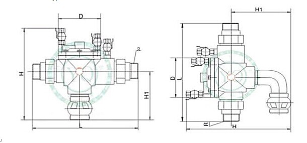
Flange Connection
|
Inside Nominal Diameter mm |
PN=1.0MPa,PN=1.6MPa |
||||||||
|
L1 Without Filtration |
L2 With Filtration |
H1 |
H |
W |
D1 |
D2 |
1.0MPa N-Φ |
1.6MPa N-Φ |
|
|
50 |
610 |
670 |
280 |
540 |
340 |
165 |
125 |
4-19 |
4-19 |
|
65 |
660 |
715 |
280 |
580 |
350 |
185 |
145 |
4-19 |
4-19 |
|
80 |
725 |
785 |
335 |
655 |
490 |
200 |
160 |
8-19 |
8-19 |
|
100 |
825 |
865 |
335 |
685 |
515 |
220 |
180 |
8-19 |
8-19 |
|
150 |
965 |
1070 |
360 |
760 |
615 |
285 |
240 |
8-23 |
8-23 |
|
200 |
1300 |
1370 |
400 |
880 |
715 |
340 |
295 |
8-23 |
12-23 |
|
250 |
1364 |
1732 |
450 |
920 |
780 |
405 |
355 |
12-23 |
12-28 |
|
300 |
1732 |
2010 |
500 |
980 |
800 |
460 |
410 |
12-23 |
12-28 |
|
350 |
1800 |
2030 |
550 |
1020 |
900 |
520 |
470 |
12-23 |
12-28 |
|
400 |
2016 |
2050 |
610 |
1200 |
920 |
580 |
525 |
16-28 |
16-31 |
Screwed Connection
|
Inside Nominal Diameter mm |
PN=1.0MPa,PN=1.6MPa |
||||
|
L |
H |
H1 |
D |
R |
|
|
15 |
265 |
245 (260) |
130 (145) |
100 |
R |
|
20 |
265 |
245 (260) |
130 (145) |
100 |
R |
|
25 |
290 |
260 (285) |
150 (165) |
110 |
R1 |
|
32 |
290 |
260 (285) |
150 (165) |
110 |
R1 |
|
40 |
325 |
285 (300) |
160 (175) |
130 |
R1 |
|
50 |
325 |
285 (300) |
160 (175) |
130 |
R2 |
Ordering Model
|
Basic Model |
Inside Nominal Diameter |
Nominal Pressure |
Material |
Illustration |
|
FC-F |
|
|
|
Backflow preventer |
|
|
50~400 |
|
|
Inside nominal diameter 50~400mm |
|
|
|
1.0 |
|
Nominal pressure 1.0MPa |
|
|
|
1.6 |
|
Nominal pressure 1.6MPa |
|
|
|
|
CZT |
Cast iron |
|
|
|
|
CZG |
Cast steel |
|
|
|
|
C304 |
304 stainless steel |