- Summary
- Parameters
- Size chart
- Model order
- Download
- Communication
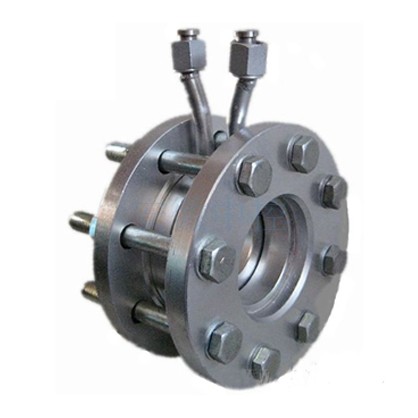
FCLG Orifice Flow meter
Overview
FCLG orifice flowmeter is the high turndown ratio differential pressure flow device which combines the standard orifice plate with multi-parameter differential pressure transmitter (or differential pressure transmitter, temperature transmitter and pressure transmitter).It can measure the flow of gas, vapor and liquid. It is widely used in petroleum, chemical industry, metallurgy, electricity, heating, water supply and other areas for process control and measurement.
Product Features
1.The structure of throttling device is easy to copy, simple, solid, stable and reliable performance, long life, low price.
2.The calculation of orifice is using international standards and processing.
3.Wide ranges of applications, could measure all single-phase flow, some mixed phase flow can also be applied
4.With standard throttling device, needs no real flow calibration, then it can be put into use.
Operating Principle
Placing a throttling element in the pipeline, when the fluid flows through the throttling element and occurs throttling, the difference of pressure (differential pressure) will be produced in front and rear both sides of the throttling element. When the fetch methods of fluid, working conditions, pipelines, throttle body, differential pressure are certain, the pipeline flow and differential pressure have a definite relationship. Therefore, the flow can be measured by the differential pressure.
Technical Parameter
|
Typical Application |
The flow measurement of high temperature and high pressure liquid, gas and vapor. |
|
Nominal Diameter |
DN15 |
|
Nominal Pressure |
PN≤40MPa |
|
Working Temperature |
|
|
Accuracy Level |
Grade 0.5, grade 1.0 |
|
Material |
(Throttling device) Stainless steel, (flange. ring casing) Stainless steel, carbon steel for choosing. |
Ordering model
|
Basic Model |
Nominal Diameter |
Nominal Caliber |
Structure Mode |
Medium |
Compensation Mode |
Illustration |
|
FCLG |
|
|
|
|
|
Orifice flowmeter |
|
|
0.25~32 |
|
|
|
|
PN0.25~32MPa |
|
|
|
10~1600 |
|
|
|
DN10~1600mm |
|
|
|
|
H |
|
|
Standard orifice (ring casing) |
|
|
|
|
Y |
|
|
Standard orifice (flange) |
|
|
|
|
K |
|
|
Standard orifice (drill hole) |
|
|
|
|
I |
|
|
ISA1932 Nozzle |
|
|
|
|
L |
|
|
Long diameter nozzle |
|
|
|
|
W |
|
|
Venturi nozzle |
|
|
|
|
G |
|
|
Typical venturi tube |
|
|
|
|
S |
|
|
Dual orifice |
|
|
|
|
Q |
|
|
|
|
|
|
|
Z |
|
|
Cone-shaped inlet orifice |
|
|
|
|
R |
|
|
1/4 round orifice |
|
|
|
|
P |
|
|
Eccentric orifice |
|
|
|
|
N |
|
|
Entire orifice |
|
|
|
|
X |
|
|
Wedge-shaped orifice |
|
|
|
|
|
1 |
|
Liquid |
|
|
|
|
|
2 |
|
Gas |
|
|
|
|
|
3 |
|
Vapor |
|
|
|
|
|
4 |
|
High temperature liquid |
|
|
|
|
|
|
N |
Without pressure/ temperature compensation |
|
|
|
|
|
|
P |
With pressure compensation output |
|
|
|
|
|
|
T |
With temperature compensation output |
|
|
|
|
|
|
Q |
With temperature and pressure compensation output |