- Summary
- Parameters
- Size chart
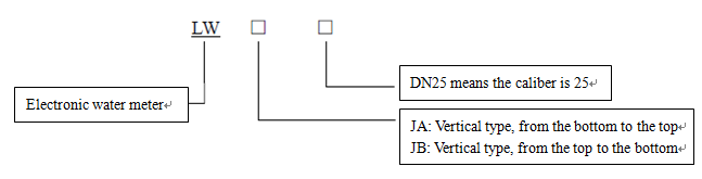
- Model order
- Download
- Communication
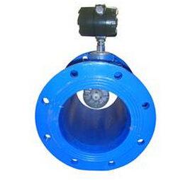
LW Intelligent Electronic Water Meter
Overview
Intelligent electronic water meter is improved on the basis of the traditional meter. The primary meter is traditional water meter structure. The counter is electronic digital display with a variety of output functions. It is mainly used in water meter measurement which needs the remote transmission or connection with the microcomputer network. Such as pure water in food industry, softened water, groundwater, tap water metering, and so on.
Working Principle
It is improved on the basis of the traditional meter that increases the magnetic material in the water impeller structure. Remove the upper pole of traditional water meter and change it to Wiggin magnetic sensor. When water impeller is rotating, it will cut magnetic line of force, generating an electrical signal. Wiggin magnetic sensor collects the number of pulses which is converted into flow by the electronic counter through the amplification, filtering, shaping.
Features
1. For non-conductive, non-viscosity water, such as pure water, filtered water, soft water, the micro flow can be measured. With long life, low failure rate.
2. It solves the remote transmission problems of traditional water meter. With various output methods, such as 4-20MA, pulse, RS485, Mudbus, Hart protocol. It solves the problem of uploading to the microcomputer.
3. Low-power consumption, field power supply with internal lithium battery. It changes mechanical display of traditional meter into a digital display, which is intuitive and accurate.
Main Technical Parameters
|
Error of Flow Measurement |
a. From included minimum flow (qmin) to the low area that excludes the boundary flow (qt) is ±5%. b. From included boundary flow (qt) to the high area that includes the upload flow is ±3% (qs) |
|
Working Pressure and Temperature |
P≤1.6MPa T≤ |
|
Power Supply |
a. 3.6V Internal lithium battery power supply, power dissipation≤1mw; b. b. 12VDC external power supply, power dissipation≤2w. |
|
Signal Output |
4~20mA, pulse, RS-485, 32,Mudbus, Hart protocol |
|
Range of Flow Velocity |
0.1~15m/s |
|
Pressure Loss |
△P≤30kpa |
Installing Boundary and Dimension
.jpg)
|
Nominal Diameter |
I |
L |
L1 |
B |
H |
Connection Thread |
|
|
mm |
D |
d |
|||||
|
15 |
204 |
110 |
1.6 |
69.4 |
48.1 |
G3/4B |
R1/2 |
|
20 |
234 |
130 |
1.6 |
69.4 |
48.1 |
G1B |
R3/4 |
|
25 (Qn2.5) |
250 |
130 |
1.6 |
69.4 |
51.1 |
G1-1/4B |
R1 |