- Summary
- Parameters
- Size chart
- Model order
- Download
- Communication
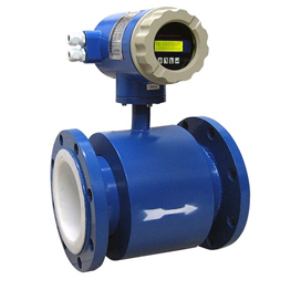
Overview
Operating Principle
Features
8. Not measurable for gas and non-conducting liquids.
Main Technical Parameters
|
Flow Measurement Range and Turndown Ratio |
Display turndown ratio 1: 150, Accuracy turndown ratio Grade 0.3 1: 4, Grade 0.5 1: 10, Grade 1.0 1: 20 |
|
Velocity range |
0.3~15m/s |
|
Medium conductivity |
≥5μs/cm |
|
Measurement Accuracy |
Grade 0.3, Grade 0.5, Grade 1.0 |
|
Medium Temperature |
-20℃~60℃, -20℃~90℃, -20℃~100℃, -20℃~180℃ |
|
Pressure |
1.6, 2.5, 6.4, 16, 26, 42Mpa |
|
Operating Environment |
Temperature -20℃~+ |
|
Output Signal |
Frequency output 0-5KHz Voltage output 1-5V Current output 4~20mA, RS-485 serial interface or RS232 interface, Mudbus protocol Hart protocol |
|
Data storage time for outage
|
10 years |
|
Power supply |
①Outer supply 220VAC±15%; ②Outer supply 24VDC±5% (Optional) ③Lithium battery power supply |
|
Power Dissipation |
≤15w (Outer power supply) |
|
Protection Level |
IP67, IP68 (Only adapt to the separated type) |
|
Lining Material |
Polyurethane rubber, Chloroprene rubber, Polytetrafluoroethylene, F46 and so on. |
|
Electrode Material |
316L, Hastelloy HB, Hastelloy HC, Titanium, Platinum and so on. |
|
Special Electrode Material |
For example: Titanium, Tantalum, Platinum and other rare metal materials |
|
Installing Type |
Integrated type, Separated type (wall mounting type) |
|
Explosion-proof Level |
ExmdibIIBT4 |
|
Flow Range |
||||||||
|
Inner diameter (mm) |
10 |
15 |
20 |
25 |
32 |
40 |
50 |
65 |
|
Qmin (m3/h) Qmax (m3/h) |
0.0283 4.24 |
0.0636 9.54 |
0.12 16.96 |
0.176 26.5 |
0.29 43.42 |
0.452 67.85 |
0.7 106.0 |
1.19 179.0 |
|
Inner diameter (mm) |
80 |
100 |
125 |
150 |
200 |
250 |
300 |
350 |
|
Qmin (m3/h) Qmax (m3/h) |
1.8 271.0 |
2.82 424.0 |
4.41 662.0 |
6.36 954.0 |
11.3 1690 |
17.6 265.0 |
25.4 381.0 |
34.6 5190 |
|
Inner diameter (mm) |
400 |
450 |
500 |
550 |
600 |
700 |
800 |
900 |
|
Qmin (m3/h) Qmax (m3/h) |
45.2 6780 |
57.2 8570 |
77.6 10600 |
85.5 12800 |
101.0 15200 |
138.0 20700 |
180.0 27100 |
229.0 34300 |
|
Inner diameter (mm) |
1000 |
1100 |
1200 |
1400 |
1600 |
1800 |
2000 |
2200 |
|
Qmin (m3/h) Qmax (m3/h) |
282.0 42400 |
342.0 51300 |
407 61000 |
554.1 83121 |
732.7 108566 |
916.0 137404 |
1131.0 169635 |
1368.4 205258 |
.jpg)
|
DN (mm) |
10 |
15 |
20 |
25 |
32 |
40 |
50 |
65 |
|
a |
230 |
230 |
230 |
230 |
230 |
230 |
230 |
230 |
|
D |
300 |
300 |
300 |
300 |
350 |
350 |
350 |
350 |
|
DN (mm) |
80 |
100 |
125 |
150 |
200 |
250 |
300 |
350 |
|
a |
230 |
230 |
280 |
280 |
310 |
360 |
460 |
460 |
|
D |
380 |
380 |
400 |
400 |
450 |
450 |
480 |
480 |
|
DN (mm) |
400 |
450 |
500 |
600 |
700 |
800 |
900 |
1000 |
|
a |
460-500 |
460-550 |
600-550 |
600 |
700 |
800 |
900 |
1000 |
|
D |
600 |
600 |
650 |
650 |
700 |
750 |
800 |
850 |
|
DN (mm) |
1200 |
1400 |
1600 |
1800 |
2000 |
2200 |
|
|
|
a |
1200 |
1400 |
1600 |
1800 |
2000 |
2200 |
|
|
|
D |
1020 |
1150 |
1250 |
1350 |
1500 |
1650 |
|
|
|
Model |
D |
A |
B |
P |
C |
E |
G |
H |
I |
F |
K |
Illustration |
|
Inside Nominal Diameter |
Medium Temperature |
Accuracy |
Nominal Pressure |
Pipe Connection Way |
Structure Mode |
Output Signal |
Power Supply |
Lining |
Electrode Material |
|||
|
LDG |
|
|
|
|
|
|
|
|
|
|
|
Electromagnetic flowmeter |
|
|
D10~2500 |
|
|
|
|
|
|
|
|
|
|
10~2500 |
|
|
|
A1 |
|
|
|
|
|
|
|
|
|
General type |
|
|
|
A2 |
|
|
|
|
|
|
|
|
|
High temperature type |
|
|
|
A3 |
|
|
|
|
|
|
|
|
|
Super high temperature type |
|
|
|
|
B1 |
|
|
|
|
|
|
|
|
Grade 0.3 |
|
|
|
|
B2 |
|
|
|
|
|
|
|
|
Grade0.5 |
|
|
|
|
B3 |
|
|
|
|
|
|
|
|
Grade1.0 |
|
|
|
|
|
P1 |
|
|
|
|
|
|
|
0.6 |
|
|
|
|
|
P2 |
|
|
|
|
|
|
|
1.0 |
|
|
|
|
|
P3 |
|
|
|
|
|
|
|
1.6 |
|
|
|
|
|
P4 |
|
|
F |
|
|
|
|
6.3 |
|
|
|
|
|
P5 |
|
|
I |
|
|
|
|
10 |
|
|
|
|
|
P6 |
|
|
R |
|
|
|
|
16 |
|
|
|
|
|
P7 |
|
|
H |
|
|
|
|
26 |
|
|
|
|
|
P8 |
|
|
|
A |
|
|
|
42 |
|
|
|
|
|
|
C1 |
|
|
B |
|
|
|
Flange form |
|
|
|
|
|
|
C2 |
|
|
|
|
|
|
Flange clamp form |
|
|
|
|
|
|
|
E1 |
|
|
|
|
|
Integrated type |
|
|
|
|
|
|
|
E2 |
|
|
|
|
|
Separated type |
|
|
|
|
|
|
|
|
G1 |
|
|
|
|
4-20mA |
|
|
|
|
|
|
|
|
G2 |
|
|
|
|
Impulse or equivalent |
|
|
|
|
|
|
|
|
G3 |
|
|
|
|
RS485 RS232Mudbus |
|
|
|
|
|
|
|
|
G4 |
|
|
|
|
Hart protocol output |
|
|
|
|
|
|
|
|
|
H1 |
|
|
|
24VDC |
|
|
|
|
|
|
|
|
|
H2 |
|
|
|
220VAC |
|
|
|
|
|
|
|
|
|
H3 |
|
|
|
Lithium battery-powered |
|
|
|
|
|
|
|
|
|
|
I1 |
|
|
Ordinary type |
|
|
|
|
|
|
|
|
|
|
I2 |
|
|
Explosion-proof type |
|
|
|
|
|
|
|
|
|
|
|
F1 |
|
Polyurethane rubber |
|
|
|
|
|
|
|
|
|
|
|
F2 |
|
Chloroprene rubber |
|
|
|
|
|
|
|
|
|
|
|
F3 |
|
Polytetrafluoroethylene |
|
|
|
|
|
|
|
|
|
|
|
F4 |
|
F46 |
|
|
|
|
|
|
|
|
|
|
|
|
K1 |
|
|
|
|
|
|
|
|
|
|
|
|
|
|
Hastelloy HB |
|
|
|
|
|
|
|
|
|
|
|
|
K3 |
Hastelloy HC |
|
|
|
|
|
|
|
|
|
|
|
|
K4 |
Special materials |