- Summary
- Parameters
- Size chart
- Model order
- Download
- Communication
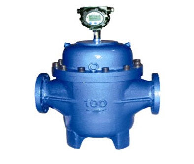
UF Dual-rotor Flowmeter
Overview
UF Dual-rotor Flowmeter (hereinafter it is abbreviated as flowmeter), also known as twin-screw flowmeter, it is one kind of volumetric flowmeters. One pair of helical rotors is the only movable body in metering chamber, to segment, estimate, transport and drain measured liquid. This flowmeter increases the positioning gear in the structure, so there is no contact between the two rotors during rotation. When the flowmeter works with a stable rotation, it has low noise, low abrasion, high accuracy, good viscosity adaptability. It allows subparticles in the measured liquid to pass through, thus the meter will seldom be jammed.
Features
1. It is suitable for thin oil, light oil, heavy oil, crude oil with high sediment concentration or large water content, measured liquid with a large range of viscosity.
2. The maximum flow rate of liquid which flows through the flowmeter is equal to twice as the flow rate of ordinary volumetric meter with same size.
3. Long service life, high accuracy and good reliability.
4. Minimal pressure loss.
5. With two kinds of counters, mechanical counter and electronic counter, a variety of output options. Such as pulse, equivalent, 4-20MA, RS485, Hart protocol and so on.
6. Intrinsic safety and explosion-proof iaⅡCT4 (intrinsically safe); explosion-proof dⅡBT4 (flame-proof); protection IP65.
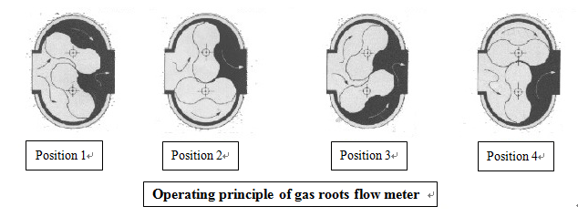
Operating Principle
As shown below, the flowmeter via a pair of rotative special screw rotors to measure the volume of the liquid flow directly.
The measurement of the flowmeter for the fluid flow is completed in the measuring chamber. A pair of screw rotors to rotate are driven by the pressure of the liquid, the enclosed space formed between the wall of the metering chamber and the rotors (shaded portions in figure), in every rotary, it discharges eight times of the shadow volume. Therefore, according to this flow relationship, as long as calculate the number of rotor rotation, you can calculate the cumulative amount of flow, according to the number of rotation per second, you can calculate the instantaneous flow.
Main technical parameter
|
Inside Nominal Diameter (mm) |
15~400 |
|
Accuracy |
Grade 0.1, grade 0.2, grade 0.5 |
|
Pressure Loss |
0~1000mpas<80kpa |
|
Working Pressure |
1.6, 2.5, 4.0, 6.3, 10, 16, 20, 42MPa |
|
Temperature Range |
-40℃~+80℃, -40℃~+150℃, -40℃~+250℃, -40℃~+
|
|
Medium Viscosity |
0.1~1000mpa.s |
|
Environmental Condition |
temperature-30℃~+ |
|
Connecting Flange |
National standard, can also be produced according to customized flange standard. |
|
Explosion-Proof grade |
ExiaII CT4,ExdII BT4 |
Flow Range
|
Inside Nominal Diameter |
Flow range m3/h |
||
|
(mm) |
Accuracy Grade 0.5 |
Accuracy Grade 0.2 |
Accuracy Grade 0.1 |
|
15 |
0.6~3 |
1~3 |
|
|
25 |
1.5~9 |
2~6 |
|
|
40 |
4~20 |
6~18 |
9~18 |
|
50 |
6~36 |
10~30 |
15~30 |
|
80 |
10~80 |
20~70 |
30~60 |
|
100 |
20~120 |
30~100 |
45~90 |
|
150 |
40~250 |
80~240 |
100~200 |
|
200 |
60~400 |
120~360 |
160~320 |
|
250 |
100~600 |
180~540 |
240~480 |
|
300 |
150~900 |
240~720 |
300~600 |
|
400 |
300~1600 |
500~1500 |
600~1200 |
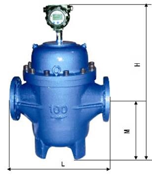
Dimension Figure
|
Nominal Diameter (mm) |
Flange Interval L |
Overall Height |
Center Height |
Installation Method |
|
H |
M |
|||
|
15 |
200 |
280 |
70 |
Horizontal type |
|
25 |
250 |
350 |
80 |
Horizontal type |
|
40 |
300 |
500 |
80 |
Horizontal type |
|
50 |
380 |
500 |
80 |
Horizontal type |
|
80 |
400 |
700 |
154 |
Horizontal, Vertical type |
|
100 |
450 |
740 |
190 |
Horizontal, Vertical type |
|
150 |
650 |
840 |
220 |
Horizontal, Vertical type |
|
200 |
700 |
1180 |
450 |
Horizontal, Vertical type |
|
250 |
1000 |
1210 |
500 |
Horizontal, Vertical type |
|
300 |
1000 |
1460 |
640 |
Horizontal, Vertical type |
|
400 |
1200 |
1700 |
700 |
Horizontal, Vertical type |
Ordering Model
|
(mm) |
Flange Interval L |
Overall Height |
Center Height |
Installation Method |
|
H |
M |
|||
|
15 |
200 |
280 |
70 |
Horizontal type |
|
25 |
250 |
350 |
80 |
Horizontal type |
|
40 |
300 |
500 |
80 |
Horizontal type |
|
50 |
380 |
500 |
80 |
Horizontal type |
|
80 |
400 |
700 |
154 |
Horizontal, Vertical type |
|
100 |
450 |
740 |
190 |
|
|
150 |
650 |
840 |
220 |
Horizontal, Vertical type |
|
200 |
700 |
1180 |
450 |
Horizontal, Vertical type |
|
250 |
1000 |
1210 |
500 |
Horizontal, Vertical type |
|
300 |
1000 |
1460 |
640 |
Horizontal, Vertical type |
|
400 |
1200 |
1700 |
700 |
Horizontal, Vertical type |
Ordering Model
|
Basic Model |
1 |
2 |
3 |
4 |
5 |
6 |
7 |
Illustration |
|
|
Counter |
Nominal Diameter |
Nominal Pressure |
Material |
Output Mode |
Working Temperature |
Accuracy |
|||
|
UF |
|
|
|
|
|
|
|
Dual-rotor flowmeter |
|
|
|
J |
|
|
|
|
|
|
Mechanical counter |
|
|
|
E |
|
|
|
|
|
|
Electronic Counter |
|
|
|
H |
|
|
|
|
|
|
Zero returning counter |
|
|
|
|
15~400 |
|
|
|
|
|
Nominal diameter 15~400mm |
|
|
|
|
|
1.6~42 |
|
|
|
|
Nominal pressure 1.6~42mpa |
|
|
|
|
|
|
C304 |
|
|
|
The rotor is made of stainless steel |
|
|
|
|
|
|
C316 |
|
|
|
The rotor is made of stainless steel |
|
|
|
|
|
|
CC304 |
|
|
|
The case and rotors are made of Stainless iron. |
|
|
|
|
|
|
CC316 |
|
|
|
The case and rotors are made of stainless steel |
|
|
|
|
|
|
|
F |
|
|
Pulse output |
|
|
|
|
|
|
|
I |
|
|
4-20mA Current output |
|
|
|
|
|
|
|
R |
|
|
RS485, Mudbus |
|
|
|
|
|
|
|
H |
|
|
Hart Protocol output |
|
|
|
|
|
|
|
|
A |
|
Working temperature -40℃~+80℃ |
|
|
|
|
|
|
|
|
B |
|
Working temperature -80℃~+350℃
|
|
|
|
|
|
|
|
|
|
0.5 |
Grade 0.5 |
|
|
|
|
|
|
|
|
|
0.2 |
Grade 0.2 |
|
|
|
|
|
|
|
|
|
0.1 |
Grade 0.1 |