- Summary
- Parameters
- Size chart
- Model order
- Download
- Communication
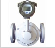
Overview
LC Oval Gear Flowmeter is the most common one of volumetric flowmeters. With a long history, it has widely used in petroleum, chemical industry, food, marine, pharmacy, papermaking and other industries. Adapt to measurements of mediums with various viscosity ranges, especially for the measurement of low viscosity medium. There are two kinds of counters: mechanical counter and electronic counter.
Features
1. Various choices of outer case material: aluminum, stainless steel, cast steel, PPS and bronze, etc;
2. Various choices of rotor: aluminum, cast iron, stainless steel, copper, Hastelloy, graphite and so on;
3. Various choices of bearing material: graphite, ceramics, hard alloy, bronze, and stainless steel with sealed bearings, etc;
4. The materials of O-shaped rings: VITON, fluorine rubber, stainless steel and Teflon, anyone can be chosen;
5. With two kinds of counters, mechanical and electronic, a variety of output modes: pulse equivalent, 4-20mA, RS485 and Hart, etc.
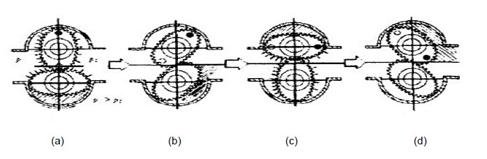
Operating Principle
Measurement of Oval Gear Flowmeter is constituted by the case, a pair of gear rotors, upper and lower cover plates, and other components, taking the cavity of a known volume between them as a measuring unit of the flowmeter. Rotor gear can be pushed to rotate by slight pressure at the inlet, and continually bring the imported liquid which is measured by cavity to the outlet. Transfer to the counter (second table) according to the number of rotations of the rotor, indicating the flow.
Main Technical Parameters
|
Inside Nominal Diameter (mm) |
8~250 |
|
Accuracy |
Grade 0.2, 0.5 |
|
Pressure Loss |
0~1000mpas<80kpa |
|
Operating Pressure |
1.6, 2.5, 4.0, 6.3, 10, 16, 20, 42MPa |
|
Temperature Range |
-20℃+ |
|
Medium Viscosity |
0.1~1000Mpa.s |
|
Environmental Conditions |
Temperature -30℃~+ |
|
Connecting Flange |
National Standard, can also be produced according to customized flange standard. |
|
Explosion-proof Grade |
ExiaII CT4,ExdII BT4 |
Flow Range
|
Inside Nominal Diameter (mm) |
Flow Range m3/h |
|
|
Accuracy: grade 0.5 |
Accuracy: grade 0.2 |
|
|
8 |
0.05~0.5 |
0.1~0.3 |
|
10 |
0.1~0.6 |
0.2~0.6 |
|
15 |
0.16~1.6 |
0.5~1.5 |
|
20 |
0.25~2.5 |
0.8~2.4 |
|
25 |
0.6~6.0 |
2~6 |
|
40 |
1.6~16 |
5~15 |
|
50 |
2.5~20 |
6~18 |
|
80 |
6~48 |
12~48 |
|
100 |
8~80 |
20~60 |
|
150 |
25~200 |
60~180 |
|
200 |
45~360 |
240~720 |
|
250 |
80~500 |
150~450 |
|
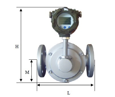
Model and Inside Nominal diameter (mm) |
L Distance Between Flanges |
Total Height |
Center Height |
Material |
Pressure Grade |
Installation Way |
|
LC 8 |
180 |
|
|
Carbon steel 304 316 |
1.6
2.5
4.0
6.3
10
26
42 |
Horizontal type |
|
LC 10 |
180 |
260 |
50 |
|||
|
LC 15 |
180 |
260 |
60 |
|||
|
LC 20 |
240 |
300 |
100 |
|||
|
LC 25 |
240 |
300 |
100 |
|||
|
LC 40 |
280 |
350 |
150 |
|||
|
LC 50 |
280 |
350 |
150 |
|||
|
LC 80 |
400 |
500 |
250 |
|||
|
LC 100 |
400(560) |
600 |
300 |
|||
|
LC 150 |
650(700) |
700 |
350 |
1.6 2.5 4.0 6.3 |
||
|
LC 200 |
1000(800) |
700 |
350 |
|||
|
LC 250 |
1000 |
800 |
700 |
Ordering Models
|
Basic Model |
1 |
2 |
3 |
4 |
5 |
6 |
7 |
Illustration |
|
|
Counter |
Inside Nominal diameter |
Nominal Pressure |
Material |
Output Method |
Operating Temperature |
Accuracy |
|||
|
LC |
|
|
|
|
|
|
|
Oval Gear Flowmeter |
|
|
|
J |
|
|
|
|
|
|
Mechanical counter |
|
|
|
E |
|
|
|
|
|
|
Electronic counter |
|
|
|
H |
|
|
|
|
|
|
Back to zero counter |
|
|
|
|
8~250 |
|
|
|
|
|
Inside nominal diameter 8~250mm |
|
|
|
|
|
1.6~42 |
|
|
|
|
Nominal pressure 1.6~42mpa |
|
|
|
|
|
|
C304 |
|
|
|
Rotor: 304 stainless steel |
|
|
|
|
|
|
C316 |
|
|
|
Rotor: 316 stainless steel |
|
|
|
|
|
|
CC304 |
|
|
|
Case, rotor: 304 stainless steel |
|
|
|
|
|
|
CC316 |
|
|
|
Case, rotor: 316stainless steel |
|
|
|
|
|
|
|
F |
|
|
Pulse output |
|
|
|
|
|
|
|
I |
|
|
4-20mA Current output |
|
|
|
|
|
|
|
R |
|
|
RS485, Mudbus |
|
|
|
|
|
|
|
H |
|
|
Hart protocol output |
|
|
|
|
|
|
|
|
A |
|
Operating temperature -20℃~+ |
|
|
|
|
|
|
|
|
B |
|
Operating temperature -20℃~+ |
|
|
|
|
|
|
|
|
|
0.5 |
Grade: 0.5 |
|
|
|
|
|
|
|
|
|
0.2 |
Grade: 0.2 |