- Summary
- Parameters
- Size chart
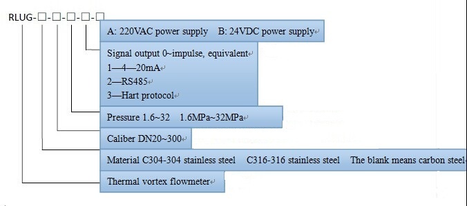
- Model order
- Download
- Communication
Operating Principle
Heating vortex flowmeter uses the measurement principles of heating type flowmeter and vortex shedding flowmeter, and puts the two principles in one. The sensor part is divided in heating type measuring element and vortex shedding measuring body. The heating type can measure small flow rate, the vortex shedding has excellent linearity for big flow rate, and the heating type vortex shedding flowmeter integrates above two merits to wide measurement range rate, at the same time, it uses the accuracy of vortex shedding flowmeter when flow rate it is big to verify heating flowmeter automatically in program and guarantee the accuracy of heating flowmeter as measuring small volume. The final measurement range rate can reach 1: 100, even more than 1:500.
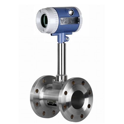
Structure: it is composed of two main parts, sensor and converter (totalizer, electronic header)
Main Technical Parameters
|
Sensor Nominal Diameter DN (mm) |
Working Pressure (MPa) |
m3/h |
Extended Flow Range m3/h |
Accuracy |
|
20 |
1.6 2.5 4.0 6.4 10 16 25 32 |
0.3~80 |
0.16~80 |
Grade 1.5 Grade 1.0
|
|
25 |
0.5~100 |
0.2~100 |
||
|
32 |
0.8~140 |
0.28~140 |
||
|
40 |
1.2~240 |
0.48~240 |
||
|
50 |
2~320 |
0.64~320 |
||
|
80 |
3~640 |
0.3~640 |
||
|
100 |
5~1100 |
2~1100 |
||
|
150 |
11~2200 |
4~2200 |
||
|
200 |
25~5000 |
10~5000 |
||
|
250 |
40~8000 |
16~8000 |
||
|
300 |
60~11000 |
22~11000 |
Dimension Fifure
|
Caliber DN (mm) |
Length L (mm) |
Center Height H (mm) |
|
20 |
280 |
300 |
|
25 |
280 |
300 |
|
32 |
300 |
300 |
|
40 |
300 |
300 |
|
50 |
350 |
300 |
|
80 |
400 |
350 |
|
100 |
450 |
350 |
|
150 |
500 |
400 |
|
200 |
650 |
500 |
|
250 |
700 |
500 |
|
300 |
800 |
500 |
|
32 |
300 |
300 |
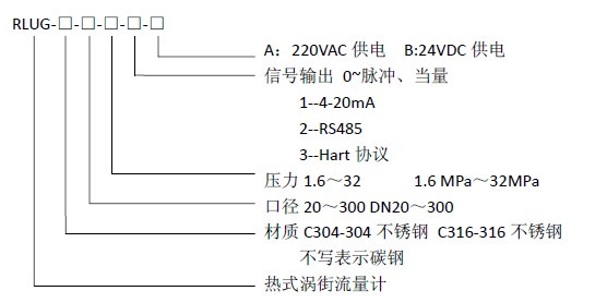 Ordering Models
|
Model |
Connection and Getting Pressure Mode |
Inside Nominal Diameter |
Shell Material |
Nominal Pressure |
Permission Working Temperature |
Illustration |
|
LX |
|
|
|
|
|
Wedge flowmeter |
|
|
A |
|
|
|
|
Thread pressure getting double-clip type |
|
|
B |
|
|
|
|
Thread pressure getting thread type |
|
|
C |
|
|
|
|
Thread pressure getting welding type |
|
|
D |
|
|
|
|
Thread pressure getting flange type |
|
|
E |
|
|
|
|
Flange pressure getting flange type |
|
|
F |
|
|
|
|
Integrated installation connecting type (temperature and pressure compensation) |
|
|
G |
|
|
|
|
Integrated installation general type |
|
|
|
15~300 |
|
|
|
Inside nominal diameter 15~300mm |
|
|
|
|
Ⅰ |
|
|
Carbon steel |
|
|
|
|
Ⅱ |
|
|
Stainless steel |
|
|
|
|
Ⅲ |
|
|
Special material and special surface treatment |
|
|
|
|
|
0.25~5 |
|
Nominal pressure 0.5~5MPa |
|
|
|
|
|
|
A |
-20~100℃ |
|
|
|
|
|
|
B |
100~250℃ |
|
|
|
|
|
|
C |
250~400℃ |