- Summary
- Parameters
- Size chart
- Model order
- Download
- Communication
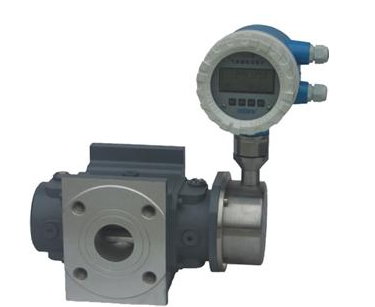
Overview
Intelligent Gas Roots Flowmeter integrates detection functions of flow,temperature and pressure. It is a new generation of flowmeter with temperature and pressure compensation. Gas is a compressible fluid; its volume was closely related to the temperature and pressure. To unify the standard in trade for both sides, the actual volume should be transformed into the standard volume (101.325 kPa 20℃) under reference conditions. In order to achieve this goal, intelligent gas roots flowmeter could modify the volume of gas precisely. It is an ideal instrument for gas measurement in petroleum, chemical industry, electricity, metallurgy and other areas.
Features
1.It’s a flowmeter which integrates high accuracy, temperature, pressure, flow sensor and intelligent volume modification. It could detect the temperature, pressure and flow of measured gas then automatically finish flow tracking compensation and the modification operation of compressibility factors.
2.It uses advanced microcomputer technology and integrated chip with high performance, has powerful overall function and remarkable performance.
3.The circuit applies surface mounting process, with a compact structure, strong interference resistance, and high reliability.
4.The pressure sensor, temperature sensor and flow sensor are built-in, to make the structure more compact.
5.Applies high and new technology with advanced micro-consumption, low overall power consumption. Could be supplied by the internal battery for longtime running, and also could be supplied by the external power source for running.
6.According to the flow frequency signal, the coefficients of the instrument could realize automatic linearity modification in segment, then to improve the using accuracy of instrument.
7.With the functions of self fault diagnosis and alarm, high reliability, uses LCD display, clear and visualized, easy for reading.
8.The flowmeter is with pulse signal output, and also could output 4~20mA standard analog signal according to the customers’ requirements.
9.The instrument is with real-time data base, it mates with our dedicated MODEM through communication interface RS -485, they could compose a telephone meter reading network, convenient for data centralized acquisition and real-time management.
10.Applies technology with advanced micro-consumption, low overall power consumption. Using internal battery can work more than 5 years.
11.Display the flow value locally, with various signal output functions, can fulfill the requirements from different scenes and systems.
12.Applies E2PROM data storage chip to save the data of users, factory parameters and some history records.
13.Applies three lines LCD with high contrast, it could display the date, standard accumulative flow, standard instantaneous flow, medium temperature, pressure value and the battery voltage.
14.With real-time data storage function, could prevent the data loss when replace the battery or power off. In the situation of power failure, the internal parameters could be preserved permanently.
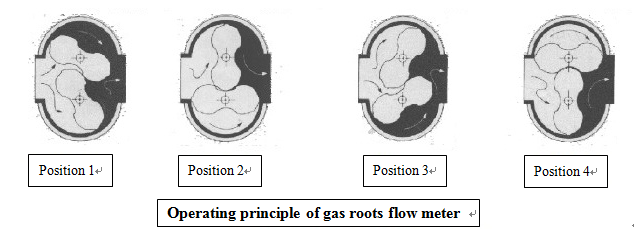
Operating Principle
Main Technical Parameters
|
Specification Model |
Nominal Diameter DN (mm) |
Upper Limit of Flow m3/h |
Startup Flow m3/h |
QMAX Pressure Loss Pa |
Nominal Pressure MPa |
Accuracy% |
Range |
Material |
|
JLQ-20 |
25 |
20 |
0.06 |
100 |
1.0 |
1.0 1.5 |
20;1 |
Aluminum alloy |
|
JLQ-30 |
40 |
30 |
0.06 |
100 |
30:1 |
|||
|
JLQ-40 |
40 |
40 |
0.06 |
140 |
40:1 |
|||
|
JLQ-60 |
50 |
60 |
0.07 |
100 |
60:1 |
|||
|
JLQ-85 |
50 |
85 |
0.07 |
140 |
70:1 |
|||
|
JLQ-100 |
80 |
100 |
0.07 |
110 |
70:1 |
|||
|
JLQ-140 |
80 |
140 |
0.07 |
150 |
120:1 |
|||
|
JLQ-200 |
80 |
200 |
0.1 |
180 |
100:1 |
|||
|
JLQ-250 |
100 |
250 |
0.12 |
180 |
110:1 |
|||
|
JLQ-300 |
100 |
300 |
0.15 |
130 |
110:1 |
|||
|
JLQ-450 |
100 |
450 |
0.15 |
200 |
110:1 |
|||
|
JLQ-650 |
150 |
650 |
0.6 |
350 |
80:1 |
Aluminum |
||
|
JLQ-1000 |
150 |
1000 |
1 |
450 |
80:1 |
Aluminum |
||
|
JLQ-1600 |
200 |
1600 |
1.2 |
500 |
80:1 |
Aluminum |
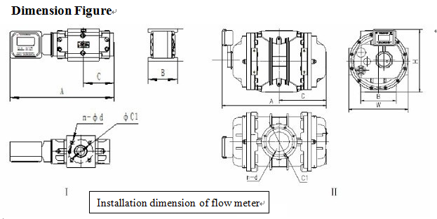
Dimension Figure
Ordering mode
|
Type Specification |
Nominal Diameter DN |
Directions of Input and output |
A (mm) |
B (mm) |
C (mm) |
W (mm) |
H (mm) |
Structural Type |
Weight (kg) |
Flange |
|
|
C1 |
n-d |
||||||||||
|
JLQ-20 |
25 |
Enter at top leave at bottom |
409 |
135 |
107 |
135 |
144 |
I, II |
9 |
Φ75 |
4-M10 |
|
JLQ-30 |
40 |
Enter at top leave at bottom |
433 |
135 |
119 |
135 |
144 |
I, II |
11 |
Φ90 |
4-M12 |
|
JLQ-40 |
40 |
Enter at top leave at bottom |
463 |
135 |
134 |
135 |
144 |
I, II |
13 |
Φ100 |
4-M12 |
|
JLQ-60 |
50 |
Enter at top leave at bottom |
470 |
180 |
137.5 |
180 |
172 |
I, II |
15 |
Φ125 |
4-M12 |
|
JLQ-85 |
50 |
Enter at top leave at bottom |
507 |
180 |
156 |
180 |
172 |
I, II |
16.5 |
Φ125 |
4-M12 |
|
JLQ-100 |
80 |
Enter at top leave at bottom |
539 |
180 |
172 |
180 |
172 |
I, II |
18 |
Φ160 |
4-M16 |
|
JLQ-140 |
80 |
Enter at top leave at bottom |
575 |
180 |
190 |
180 |
172 |
I, II |
20 |
Φ160 |
4-M16 |
|
JLQ-200 |
80 |
Enter at top leave at bottom |
569 |
210 |
187 |
210 |
245 |
I, II |
24 |
Φ160 |
4-M16 |
|
JLQ-250 |
100 |
Enter at top leave at bottom |
647 |
210 |
226 |
210 |
245 |
I, II |
30 |
Φ180 |
4-M16 |
|
JLQ-300 |
100 |
Enter at top leave at bottom |
647 |
210 |
226 |
210 |
245 |
I, II |
30 |
Φ180 |
4-M16 |
|
JLQ-450 |
100 |
Enter at top leave at bottom |
743 |
210 |
274 |
210 |
245 |
I, II |
36.5 |
Φ180 |
4-M16 |
|
JLQ-650 |
150 |
Enter at top leave at bottom |
745 |
φ285 |
275 |
370 |
380 |
I, II |
92.5 |
Φ240 |
4-M16 |