- Summary
- Parameters
- Size chart
- Model order
- Download
- Communication
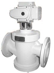
Dynamic Balance Electric Control Valve
Working Principle
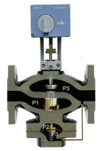
(1) When the valve inlet P1 increases, P1-P3 is increased, the automatic balancing valve will turn down through the function of the pressure sensitive diaphragm, so that to increase P1-P2, then maintain the constant of P2-P3; when the inlet P1 reduces, P1-P3 is reduced, the automatic balancing valve will turn up by the function of the spring, causing a decrease of P1-P2, to maintain the constant of P2-P3.
In the variable flow system with a large load fluctuation, when the system pressure changes:
(2) When the electric actuator receives a control signal then let the valve rod move upward or downward, it makes the valve plug up or down, the degree of opening between P2, P3 also changes. Because no matter the system differential pressure how to change, the differential pressure (P2 - P3) between P2, P3 is always the same, and therefore correspond to any open position, the water flow conveyed is certain.
Technical Parameters
|
Valve Form |
Specification |
Pressure Differential Range (PKa) |
Flow Range (m3/h) |
Working Pressure |
Flow Error |
Liquid Temperature |
|
Two Direction Link |
DN25 |
30-300 |
0.2-2.9 |
PN16 |
5% |
0 |
|
DN32 |
30-300 |
0.5-4.7 |
||||
|
DN40 |
30-300 |
1-7.7 |
||||
|
DN50 |
30-300 |
2-12.1 |
||||
|
DN65 |
30-300 |
3-20.4 |
||||
|
DN80 |
30-300 |
5-30.8 |
||||
|
DN100 |
30-300 |
10-45.3 |
||||
|
DN125 |
30-300 |
15-70.7 |
||||
|
DN150 |
30-300 |
20-101.8 |
||||
|
DN200 |
33-300 |
5.0-360 |
||||
|
DN250 |
22-210 |
4.0-460 |
Ordering model
|
Basic Model |
Nominal Diameter |
Nominal Pressure |
Material |
Illustration |
|
FCDDF |
|
|
|
Self-operated flow control valve |
|
|
25~250 |
|
|
Nominal Diameter 15~350mm |
|
|
|
1.6 |
|
Nominal Diameter 1.6Mpa |
|
|
|
|
CZT |
Cast iron |
|
|
|
|
CZG |
Cast steel |
|
|
|
|
C304 |
304 stainless steel |